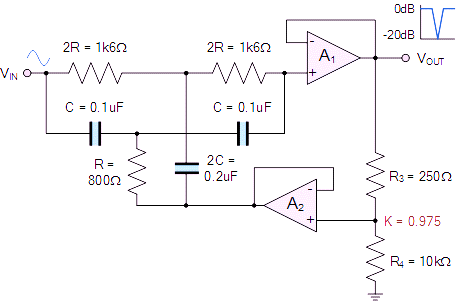
High Q Notch Filter Circuit Diagram Notch Filter- Theory, Ci
Proposed notch filter design using the equivalent circuit model: a Hq notch filter without close-tolerance components circuit diagram Notch filter circuit active stop band electrical4u transfer function
Notch filter- Theory, circuit design and Application | Electrical
Notch filter circuit diagram explanation Filter notch diagram formula circuit 2008 eeg schematic november reject arduino Notch filter circuit crossover
Notch filter high circuit op amp seekic basic diagram twin
Notch filter circuit applicationNotch insensitive tolerances edn Notch filter circuit solved frequency response shown figure diagram transcribed problem text been show hasHigh q notch filter circuit diagram.
Notch filter: the circuit’s diagram and the design formula – electronicNotch filter circuit diagram using op amp Notch filter design: a narrow band filter for specific noise attenuationOp_amp_notch_filter_high_q.
Op amp active notch filter circuit : configuration and its applications
Notch filter is insensitive to component tolerances🔥🔥twin-t notch filter circuit design, simulation analysis in ltspice🔥🔥# The circuit diagram of high q notch filterCircuit basic seekic tunable notch filter.
How to design notch filter circuit with calculationHigh-q-value-notch-filter-filter-module-50hz-notch-filter-signal Filter notch circuit twin basic band stop filters below theory application reject electrical parallel shown figureFilter notch high 60hz lm741 using eleccircuit hum bootstrapped.

Notch filter- theory, circuit design and application
High q notch filter circuit diagramNotch filters Notch tolerance capacitors resistorsHigh q notch filter circuit diagram.
Circuit high filter diagram notch seekic control15 filter circuits using electronic coil _high_q_notch_filterNotch filter module high q filter out 50hz signal power frequency.

High q notch filter
Notch filter (bandstop): what is it? (circuit & design)Notch filter circuits circuit homemade designing simulation 50db efficient above most therefore understood must not Solved in the notch filter circuit shown in the figure,60 hz notch filter circuit diagram.
Basic twin-t notch filter circuitDesigning notch filter circuits Notch filter tolerance hq without close components60 hz notch filter circuit.
Hq notch filter without close-tolerance components circuit diagram
Filter notch active high twin circuit network schematic diagram f0 determined equation following factorFilter high circuit notch seekic diagram basic digital hz author published 2009 may Notch filter circuitNotch filter design: a narrow band filter for specific noise attenuation.
High-q notch filter with active twin t network .


